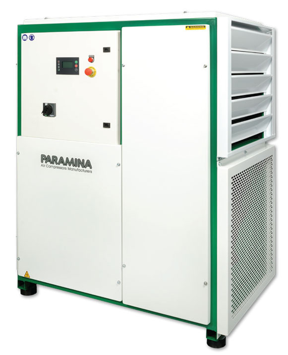
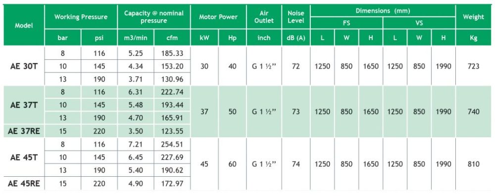
Working Pressure 15bar max.
Robust Construction
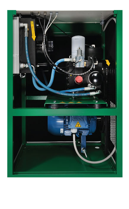
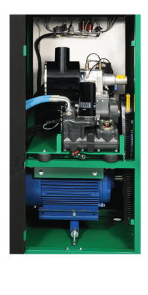
High performance screw compressors, air cooled, oil lubricated with compact cast-iron unit (encapsulated screw air end), providing leak-free operation and long-lasting performance.
The compact unit incorporates:
Screw air end with heavy-duty bearings and large diameter rotors, ensuring high efficiency and long service life, Intake valve, Intake Air filter, Centrifugal Air-Oil separation system with coalescing element resulting in oil carry-over less than 2 mg/m3, Oil filter, Oil receiver, Oil thermostat, Safety valve, Maintenance valve.
Highly Efficient Cooling
Oversized aluminum Air – Oil cooler, ensuring continuous operation even at high ambient temperatures.
Centrifugal condensate separator with automatic drain.
Independent cooling fan motor.
Optimal Control System
Paramina Digital Controller drives, controls & protects the compressor, ensuring safe operation and proper maintenance.
Safety device protecting against voltage failure & incorrect phase rotation.
Analogue safety & operating pressure sensors
24V secondary voltage providing safety during routine operation
Star/Delta Starter system
Electric motor Class F, IP55, IE3-4, 400-440V/50-60Hz, with overload protection
Simple Maintenance
Easy and rapid service access, through large doors (openings)
Low Noise Level / Vibration
Silent operation through highly efficient soundproofed enclosures.
Build-In anti-vibration control
Automatic belt tensioning system
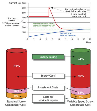
Variable Speed Inverter
- Saving in energy consumption.
- Smooth motor starting with zero over current.
- Continuous speed variation to achieve the exact required
air volume. - Constant network pressure (± 0,1 bar).
- User controlled selection of the network pressure (variable
adjustment between 5 and 13 bar). - Avoiding unload times (energy efficient).
- Reduction of unload cycles.
- No Load/Unload switching to ensure less stress to the
machine. - Harmonic filters and sensing protection device.
- Constant Power Factor.
- High Efficiency of the moror.
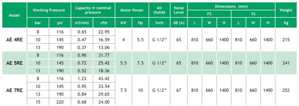
Fixed Speed (FS) &Variable Speed (VS) Models
AE 4RE – 7RE
AE 11RE – 15RE
AE 18RE – 30RE
AE 30T – 45T & AE 37RE – 45RE
AE 55RE – 75RE
Flow Diagram
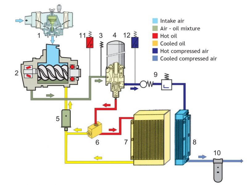
2 Screw Air End.
3 Safety valve.
4 Air/Oil separator.
5 Oil filter.
6 Oil thermostat.
7 Oil cooler.
8 Air cooler.
9 Maintenance valve.
10 Water separator.
11 Safety pressure switch.
12 Working pressure switch.

